Planer snipe: Diagnose causes and choose a safe fix
Quick answer
Planer snipe is a deeper cut near the leading or trailing end of a board. Start by marking which end is affected and whether it happens on every board or mainly on long, heavy stock. Verify the workpiece and support path first. If a repeatable defect remains on suitable scrap, follow the exact planer manual for setup checks or use authorized service; table, roller, cutterhead, and cut-depth procedures are not universal.
Common questions
- What causes planer snipe?
- Planer snipe occurs when a board moves closer to the cutterhead near entry or exit. Unsupported stock is a common cause, but an unsuitable workpiece, unstable mounting, incorrect table setup, worn parts, or a model-specific machine condition can produce a similar mark.
- Why do I get planer snipe only at the end of a board?
- Trailing-end snipe often appears as the board's weight shifts while it leaves the feed system. Check whether the stock stayed flat and level through the entire outfeed path before considering a machine adjustment.
- Will a planer snipe jig or sled fix the problem?
- A compatible carrier or sled can help support some workpieces, but it is not a universal cure. It must remain within the exact planer's material limits and cannot replace a flat reference face, guards, safe support, or manufacturer-specified setup.
Source note: This diagnostic was checked on October 14, 2026, against the current DeWalt DW735 and RIDGID R4331 manuals and OSHA woodworking-machinery requirements. Model examples show why the exact manual controls; this is not a hands-on product test.
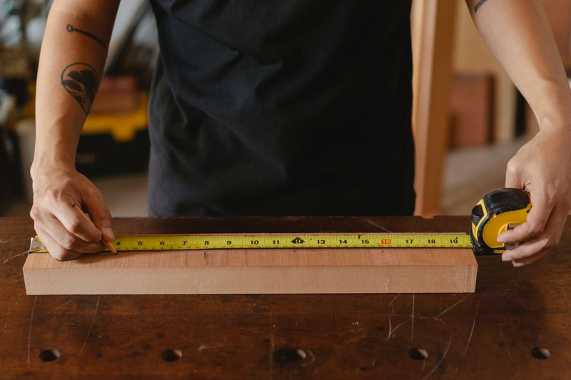
Planer snipe is a deeper cut near the leading or trailing end of a board. Do not assume one adjustment fixes every case. First mark the affected end, note when the depression begins, and compare the pattern across suitable boards.
If snipe appears mainly on long or heavy stock, check support first. If the mark repeats on every suitable board, a setup or machine condition becomes more likely. Change one variable at a time.
What planer snipe is—and what it is not
A thickness planer feeds a board between rollers and a cutterhead while its bottom face rides on the bed. If an unsupported end drops, the opposite end can rise toward the cutterhead and receive a deeper cut.
Snipe is different from:
- Tearout: torn or lifted fibers that follow grain direction rather than only the board end.
- Ridges: raised lines that can point to a nicked knife or insert.
- Chatter or scallops: repeated marks that may involve stock movement, feed trouble, or a cutter condition.
- Remaining bow or twist: a thickness planer references one face; it does not automatically establish the first flat face.
A jointer can also leave an end low, but its workpiece support and cutter relationship are different. Do not apply a jointer-table correction to a thickness planer. If the stock does not already have a suitable reference face, revisit the milling sequence in the thickness planer guide before diagnosing snipe.
Make the machine safe before inspecting it
Stop if the board stalls, kicks back, chatters, changes sound, or needs abnormal force. Turn the planer off, wait for all motion to stop, and disconnect power before clearing a jam or making an adjustment.
For every inspection and test:
- Keep guards and dust hoods installed, and keep hands away from the cutterhead, chip opening, and feed rollers.
- Stand out of the stock’s line of travel and provide clear infeed and outfeed space.
- Reject stock with loose knots, embedded metal, severe warp, or dimensions outside the exact manual’s limits.
- Wear the eye, hearing, respiratory, and other protection required by the manual, material, and workplace.
- Never reach into the machine, defeat a guard, or measure a moving board.
OSHA requires planing-machine cutterheads and feed rolls to be guarded and says woodworking knives and cutting heads must be sharp, properly adjusted, and firmly secured.
Match the snipe pattern to the first check
Mark the feed direction, both ends, top face, and reference face before sanding or trimming.
| Symptom | First cause family to check | Safe first action |
|---|---|---|
| Deeper cut at the leading end | Stock tipped as it entered, infeed support changed, or the workpiece was not flat on the bed | Reconstruct the infeed path with power disconnected; check stock and support |
| Deeper cut at the trailing end | Stock weight shifted as it exited, outfeed support changed, or the board lifted near the cutterhead | Check whether the full outfeed path kept the board supported and clear |
| Snipe at both ends | Support changed at both transitions, or a repeatable setup or machine condition is present | Verify the whole support path, then make one controlled scrap comparison |
| Mostly long or heavy boards show snipe | The unsupported length is levering the board | Add stable support permitted by the manual; do not hold the stock in a risky posture |
| Every suitable board shows the same mark | Mounting, extension-table setup, carriage behavior, knives, rollers, or another model-specific condition | Record the pattern and follow the exact manual’s inspection or service route |
| Depression occurs away from an end | It may not be snipe | Stop and diagnose stock movement, feed, cutter condition, debris, or damage separately |
The pattern narrows the search; it does not prove a cause. A bowed board can imitate a support problem, while a dirty or damaged machine can mask the effect of a technique change.
Run a controlled planer-snipe test
Use straight, stable scrap with a suitable reference face and dimensions within the exact manual’s limits. Do not test with a project part or warped stock.
- Identify the machine. Record its model, type, and serial range. Find the matching manual and note its stock limits, permitted cut, support, mounting, table, lock, and service instructions.
- Record a baseline. Mark feed direction and both ends. Record the stock, support, cut setting, and snipe location before sanding.
- Inspect with power isolated. Check that the planer is secure, the bed and support path are clear, and accessible components match the manual. Do not remove a guard or turn the cutterhead by hand unless the manual expressly provides a safe procedure.
- Correct support only. Arrange stable, clear support so the scrap can remain flat through entry and exit. Make one pass permitted by the manual with no other setup change.
- Compare the marks. If the pattern improves, repeat the support arrangement before changing anything else. If it remains in the same place on multiple suitable boards, stop routine testing and use the manual’s setup, maintenance, or authorized-service path.
Keep a simple test record:
| Test field | Record |
|---|---|
| Planer model, type, and serial range | ___ |
| Manual URL; stock size and condition | ___ |
| Leading, trailing, or both ends | ___ |
| Happens on every board or mainly long/heavy stock | ___ |
| Support path and changed variable | ___ |
| Result and next decision | ___ |
Compare common planer-snipe fixes
Choose the least complex method that addresses the observed cause.
| Method | Best fit | Limit or caution |
|---|---|---|
| Stable infeed and outfeed support | Snipe increases with board length or weight | Support must not obstruct the board, create a pinch point, or make the operator reach into the machine |
| Plane parts oversize, then trim the affected ends | The project can tolerate extra length and the machine otherwise operates safely | This manages waste; it does not correct an unsafe or worsening machine condition |
| Feed compatible boards end-to-end | Repeated parts and a manual that permits the method | Do not assume spacing, stock size, or multi-board feeding rules transfer between models |
| Compatible planer sled or carrier | Stock needs a stable carrier and the manual permits the combined dimensions and setup | Added thickness changes capacity; loose shims, stops, or fasteners can become hazards |
| Manufacturer-specified table or support adjustment | The exact manual identifies a check and the symptom matches it | Dimensions and procedures are model-specific; isolate power before adjustment |
| Authorized service | Repeatable snipe remains after stock and support pass inspection, or parts are damaged or unstable | Label the machine out of service until the condition is resolved |
There is no universal value for lifting a board end or changing a roller, table, cutterhead, or cut-depth setting. Use the method for the exact machine while staying out of the stock path.
The manuals illustrate the difference. The DeWalt DW735 has an automatic carriage lock and calls for level, flat stock with added support for especially long material. The RIDGID R4331 describes its own lock, table-leveling procedure, and end-to-end feeding guidance. Neither procedure is universal.
When stock is the real problem
A planer can press a bowed board flatter under its rollers, then release it after the cut. Severe cup, bow, or twist can also feed unpredictably and should not be used for a snipe test.
Establish the reference face by an appropriate method before thicknessing. Also let stock reach the moisture condition required for the project before final milling; the wood moisture-meter workflow explains how to document meter settings and readings without inventing a universal target.
If the planer produces consistent thickness and only a disposable end section is affected, leaving parts long may be the lowest-risk workflow. For cleanup after safe planing, compare the hand plane vs. electric planer guide and hand-plane roles.
Packed chips need attention, but suction does not correct snipe. Follow the maker’s extraction instructions and plan stationary collection with the workshop dust-collection guide.
Sources and scope
This diagnostic was checked on October 14, 2026, against these primary sources:
- DeWalt DW735 instruction manual
- RIDGID R4331 operator’s manual
- OSHA 29 CFR 1910.213 woodworking machinery requirements
Your next step
Keep the marked scrap and complete the test record. If stable support changes the result, standardize that support for the next suitable board. If the same snipe remains across suitable stock, stop changing technique and follow the exact manual’s inspection or authorized-service route.
Do not return a planer to work if a guard, roller, cutterhead, table, lock, cord, switch, or mounting point is damaged, unstable, or outside the manufacturer’s instructions.

The Carpenter's Guide Editorial Team
Independent trade-focused editorial team